TimberTech Buildings is composed of a main module, whose features are described below, and some additional modules, which can be purchased separately, including the module for the fire design of timber structural members and the module for the automatic printing of the bill of quantities.
Graphical user interface
The 3D graphical interface allows you to quickly and efficiently define the structural model.
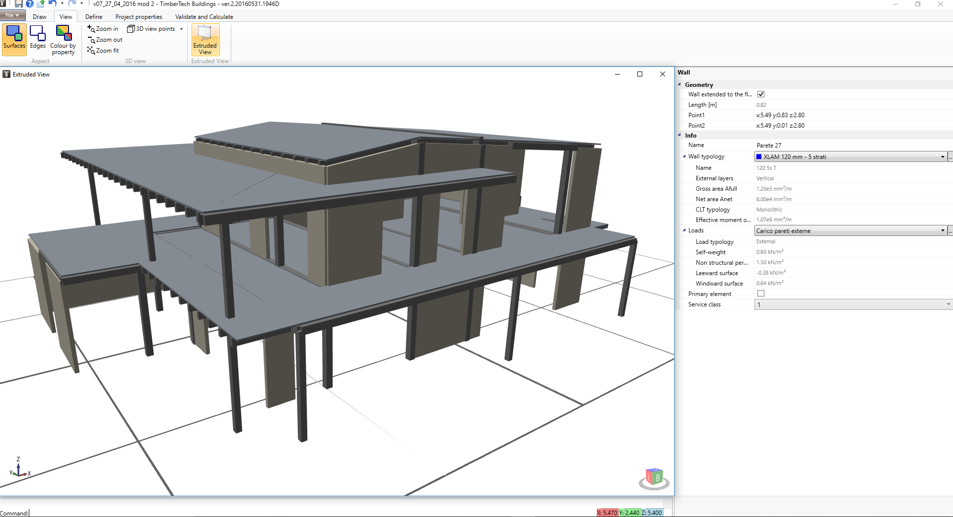
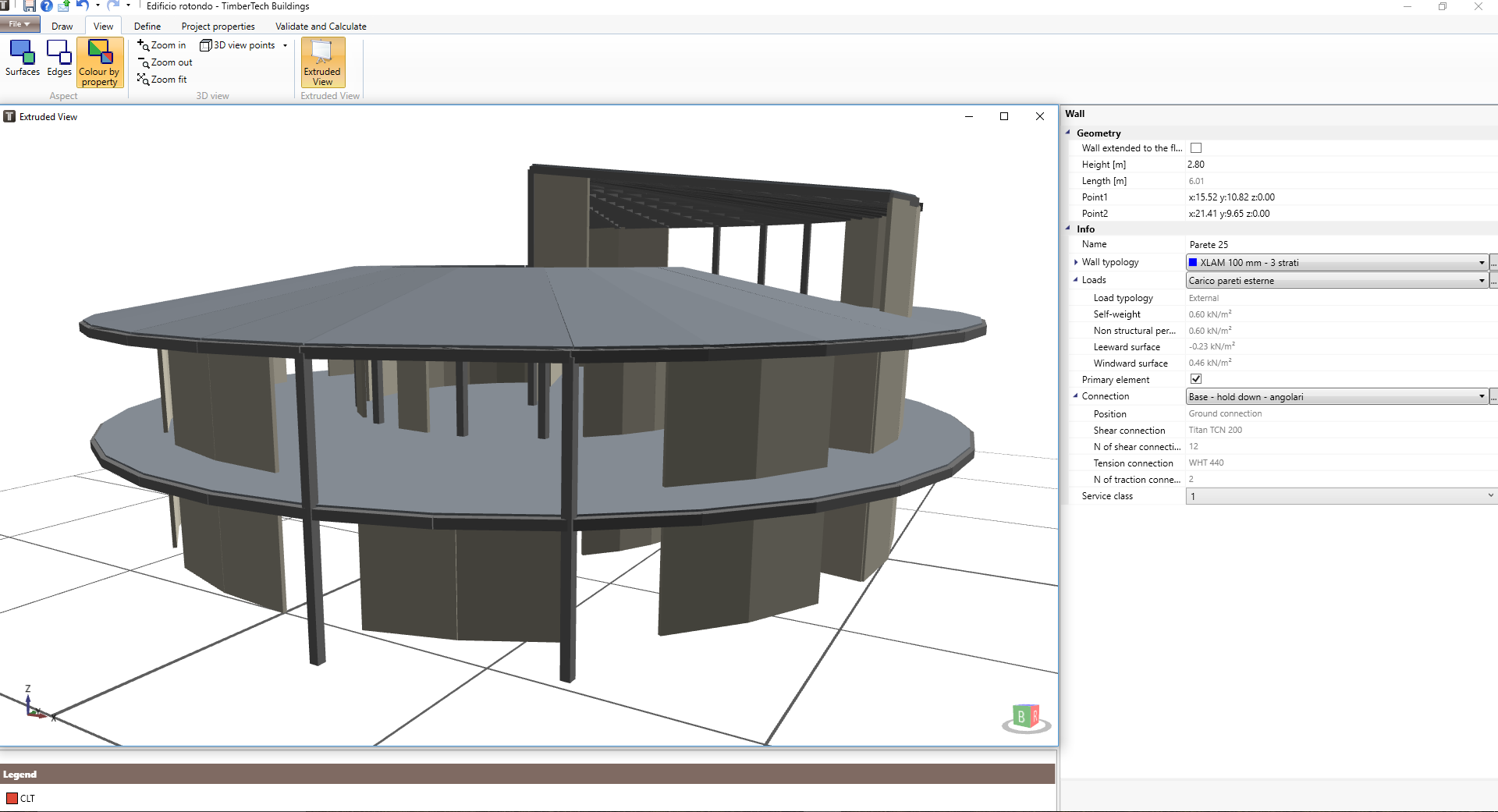
3D VIEWER AND BIM
The 3D Viewer allows the extruded view of the structural members for more control over modeling and BIM technology ensures greater efficiency and productivity.
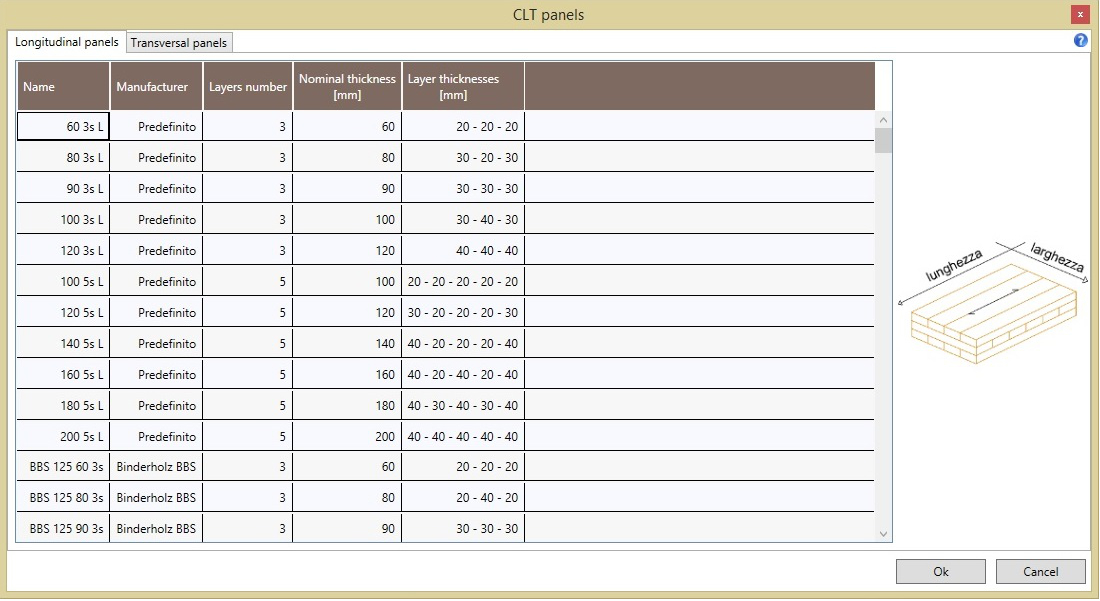
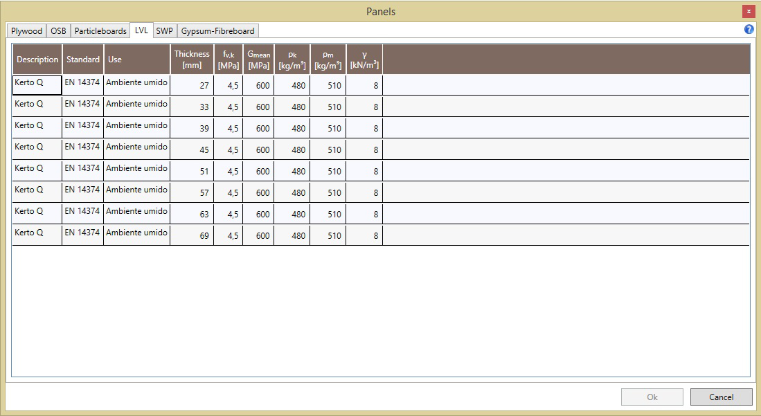
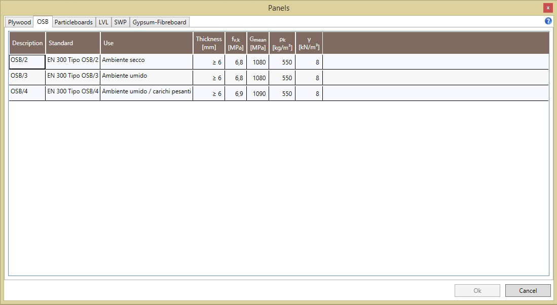
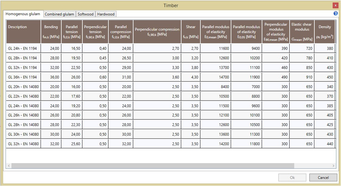
timber material databases
The physical-mechanical and geometrical properties of the timber construction elements and wooden materials are preloaded in the software. For example you can finde the products of the leading manufacturers of CLT panels (Binderholz, Stora Enso, KLH, LENO, Mayr Melnhof, Rubner Holzbau, XLAM Dolomiti, Essepi, Diemme Legno, L.A. COST, Area Legno, Artuso Legnami, Calet, Hasslacher Norica Timber, Holz Albertani).
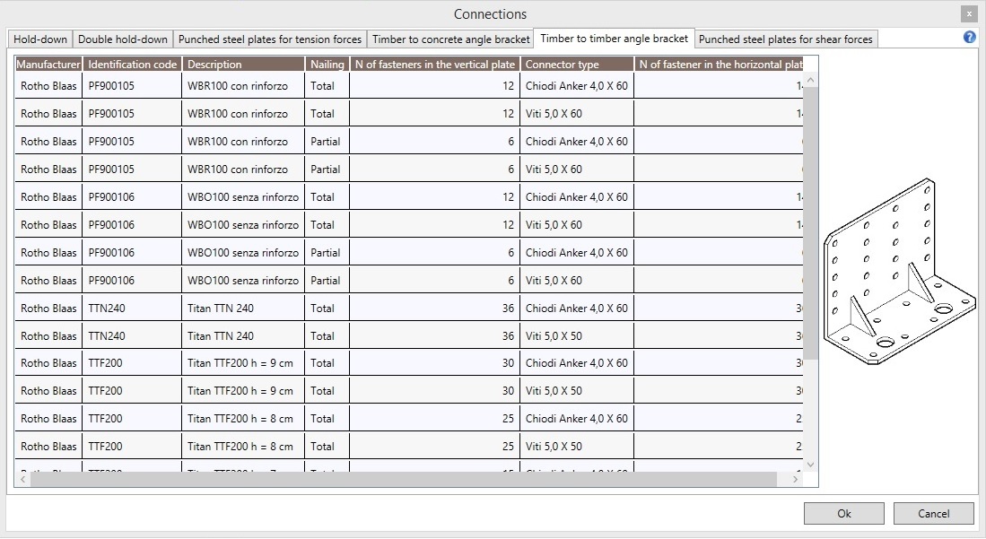
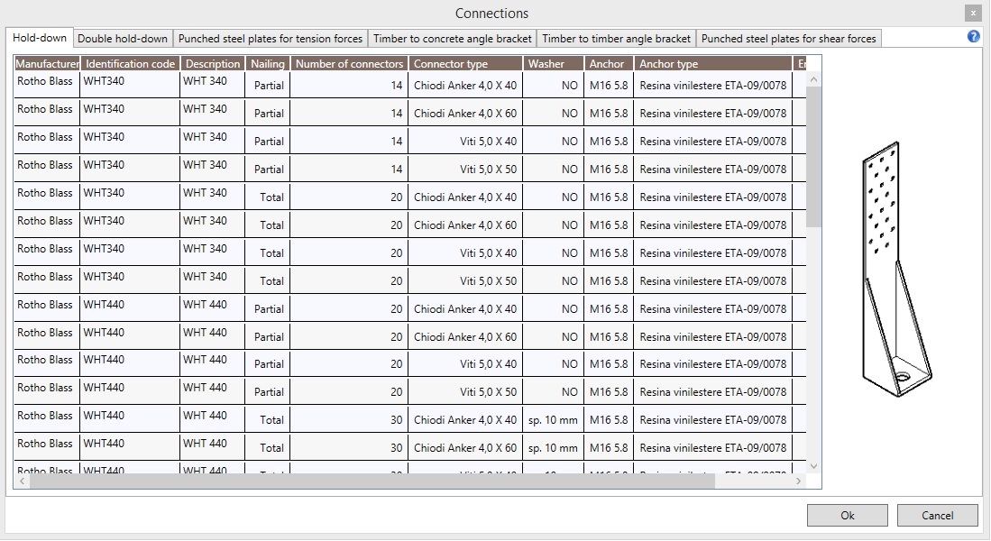
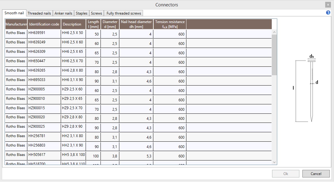
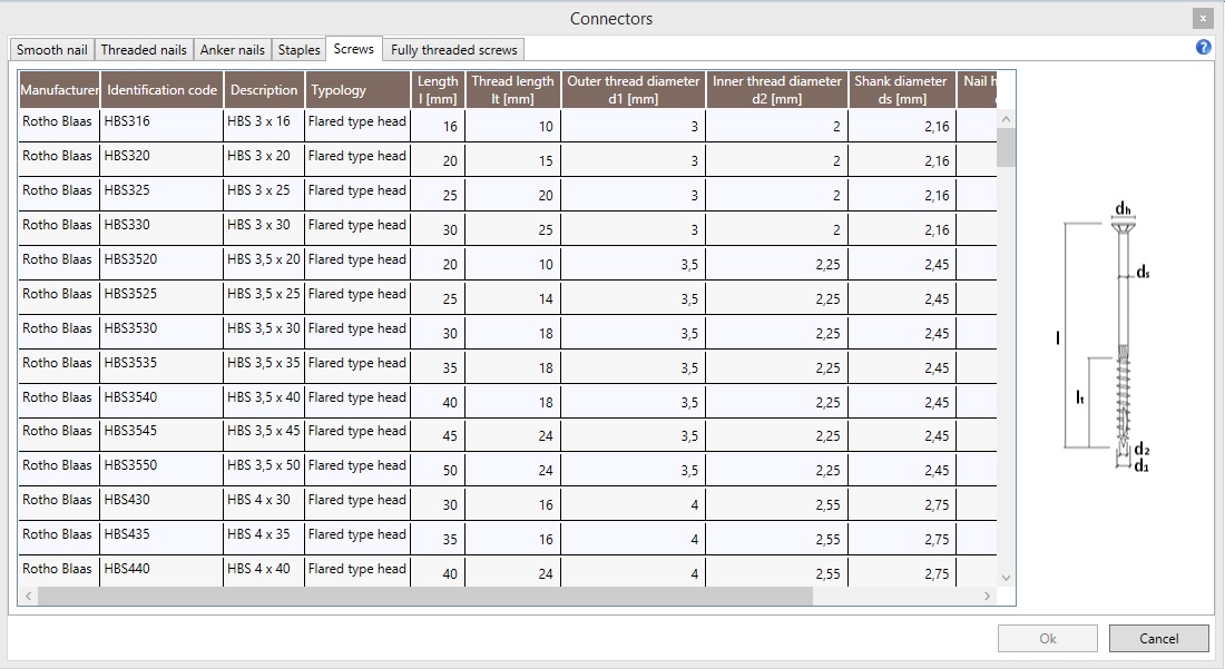
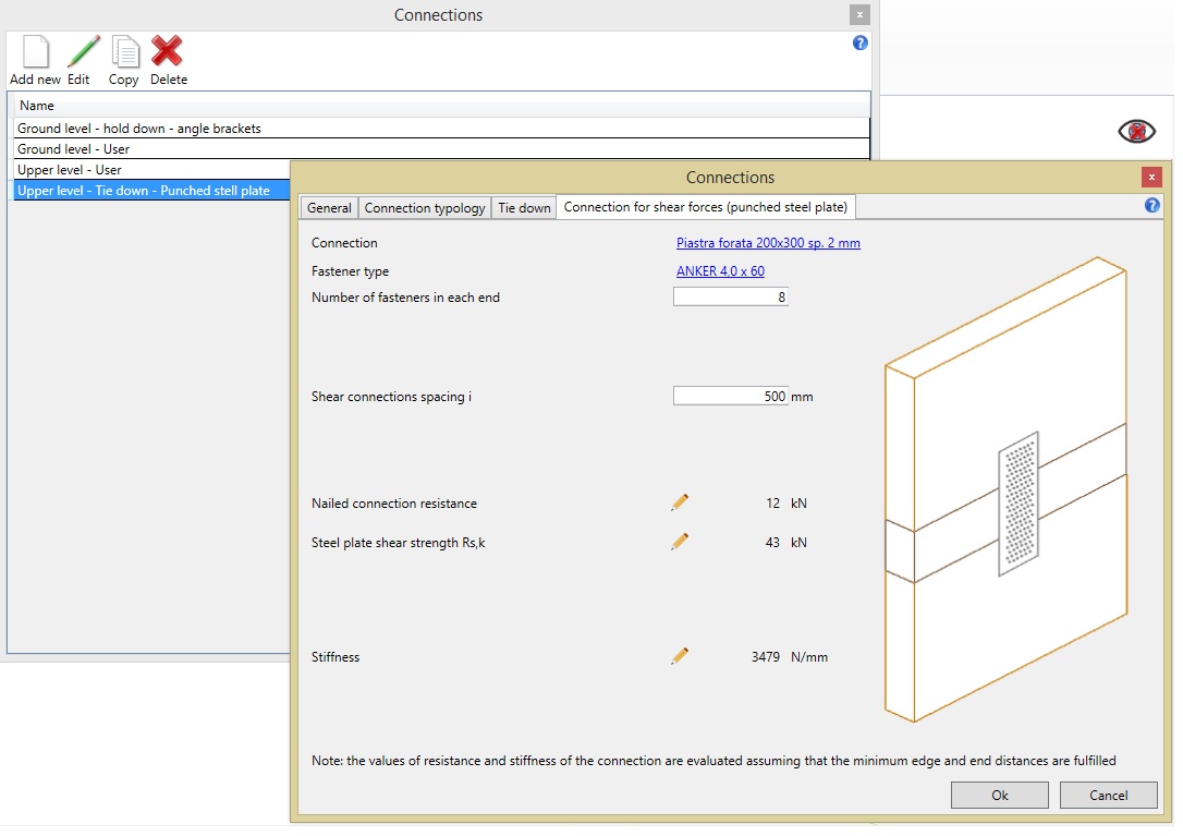
Connections database
There are internal databases with the characteristics of the products of the main European manufacturers (Rotho Blass, Wuerth, Simpson StrongTie, Borga Italia, Roofrox). The user can also customize existing connections changing their strength and stiffness.
You can choose different types of fasteners: smooth nails, threaded nails, anker nails, staples, screws and fully threaded screws.
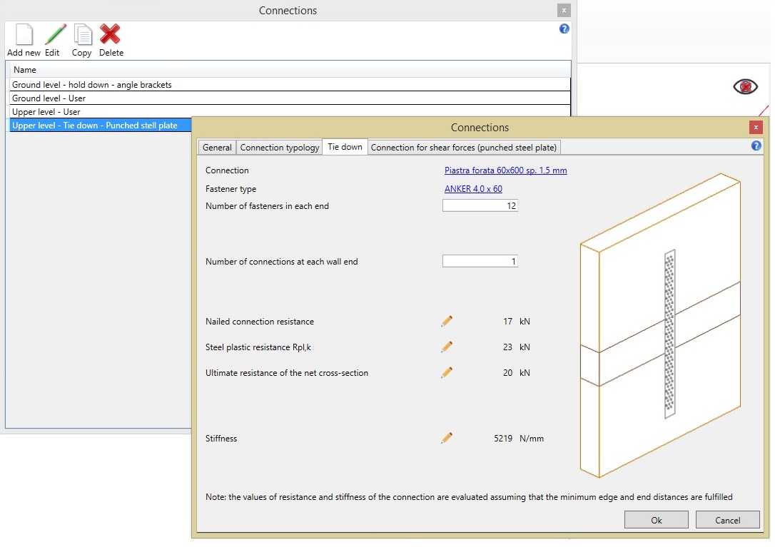
You can also choose different types of connections: single and double hold-down, punched metal platers for tesnsion forces, timber-to-concrete angle brackets, timber-to-timber angle brackets, punched metal plates for shear forces.
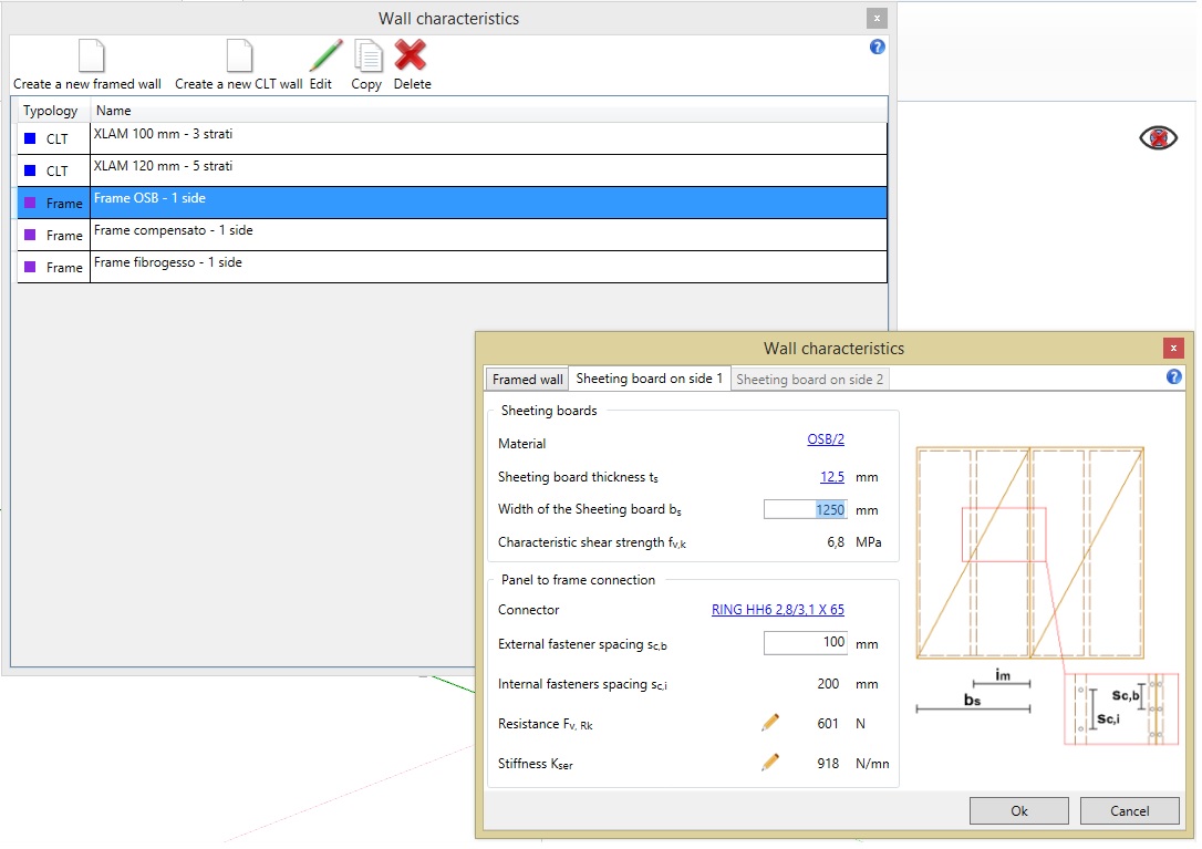
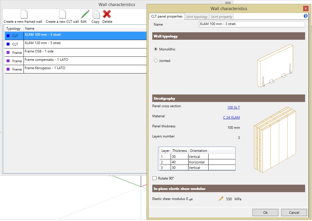
Defining the WALL properties
The software guides the user in the definition of the geometrical and mechanical properties of the CLT and famed walls.


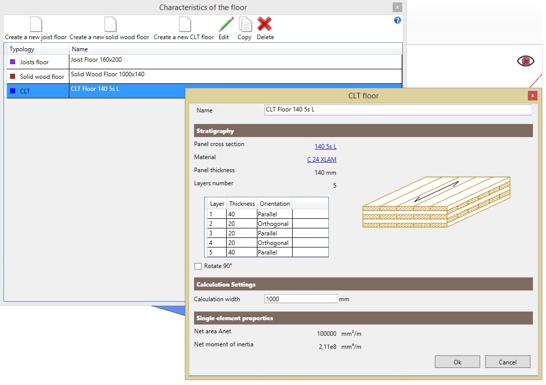
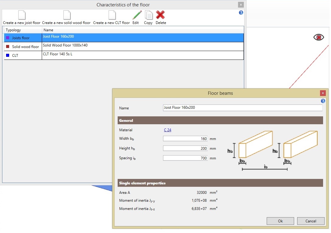
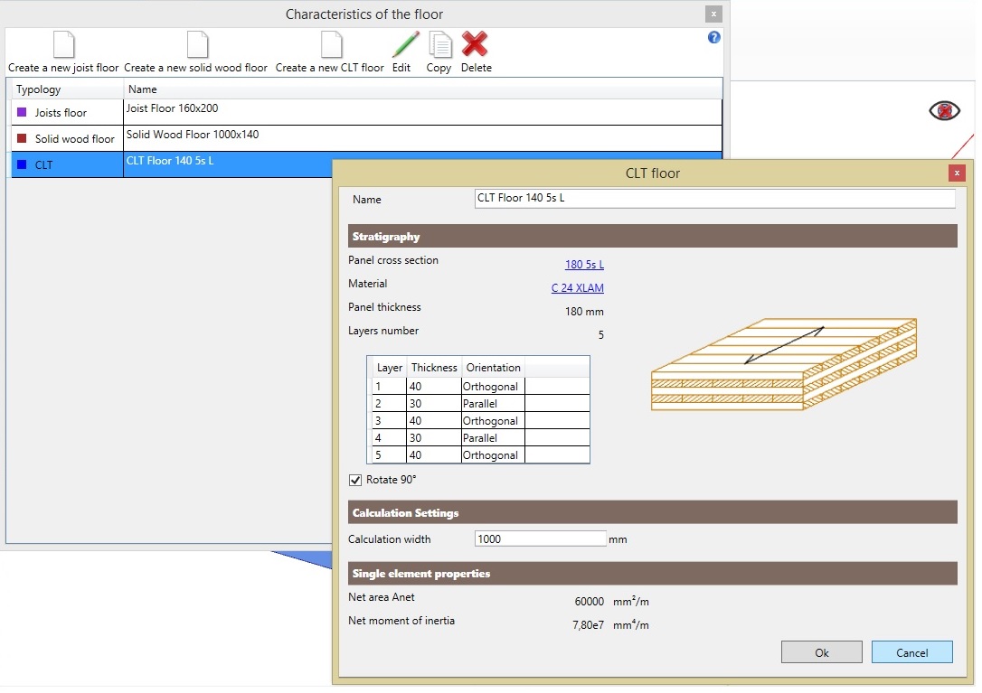
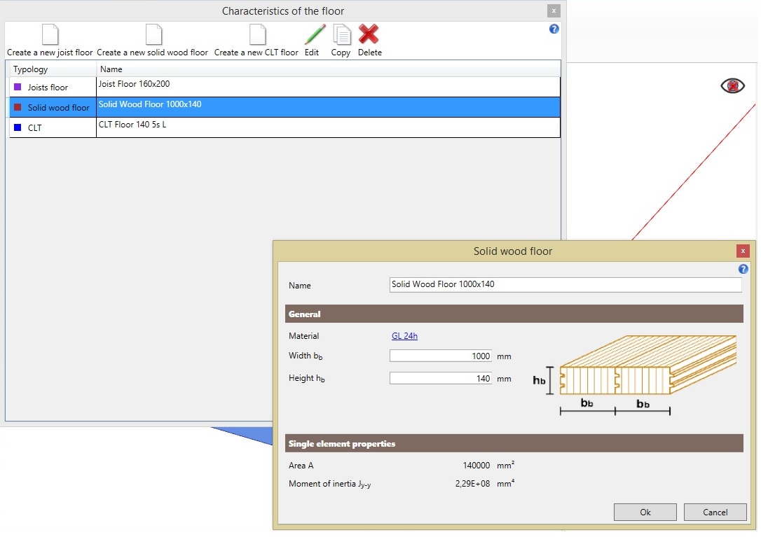
DEFINING THE CEILING PROPERTIES
The software guides the user in the definition of the geometrical and mechanical properties of the ceilings: joist floors, solid timber floors and CLT floors.
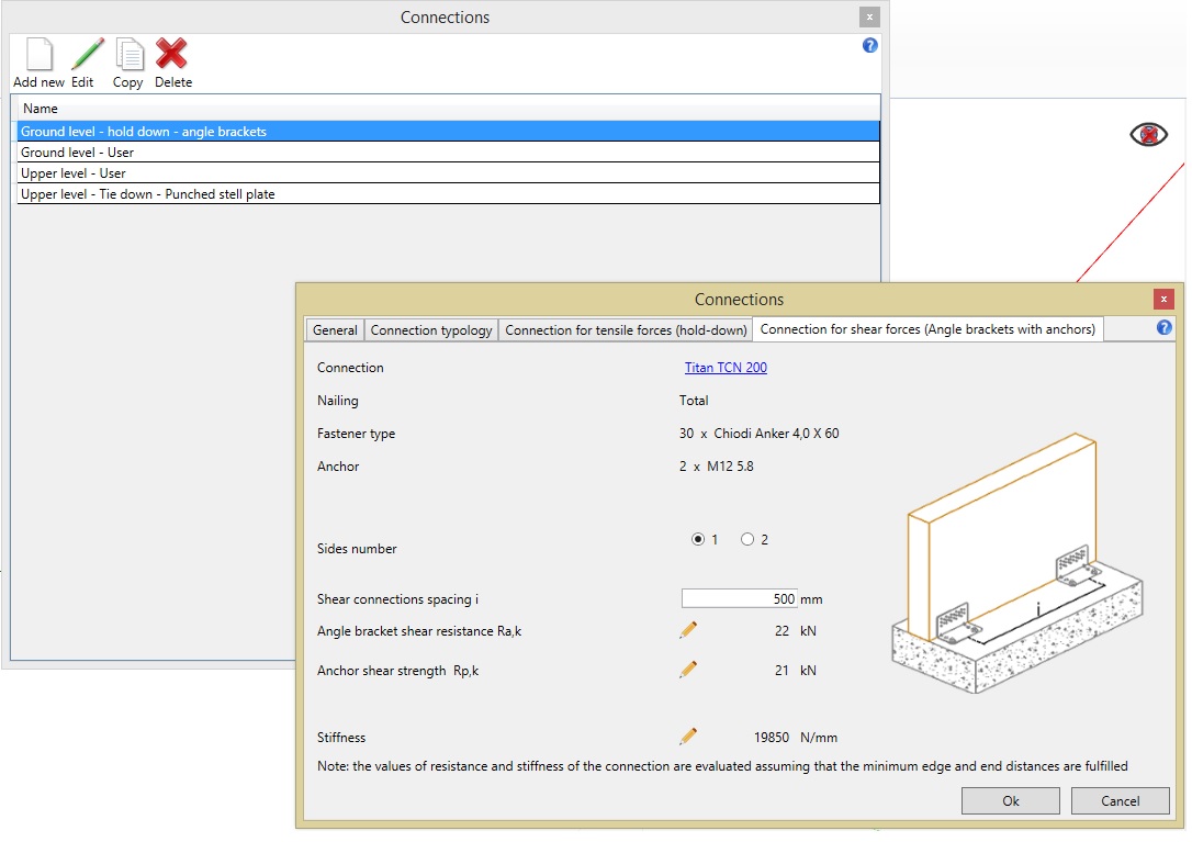
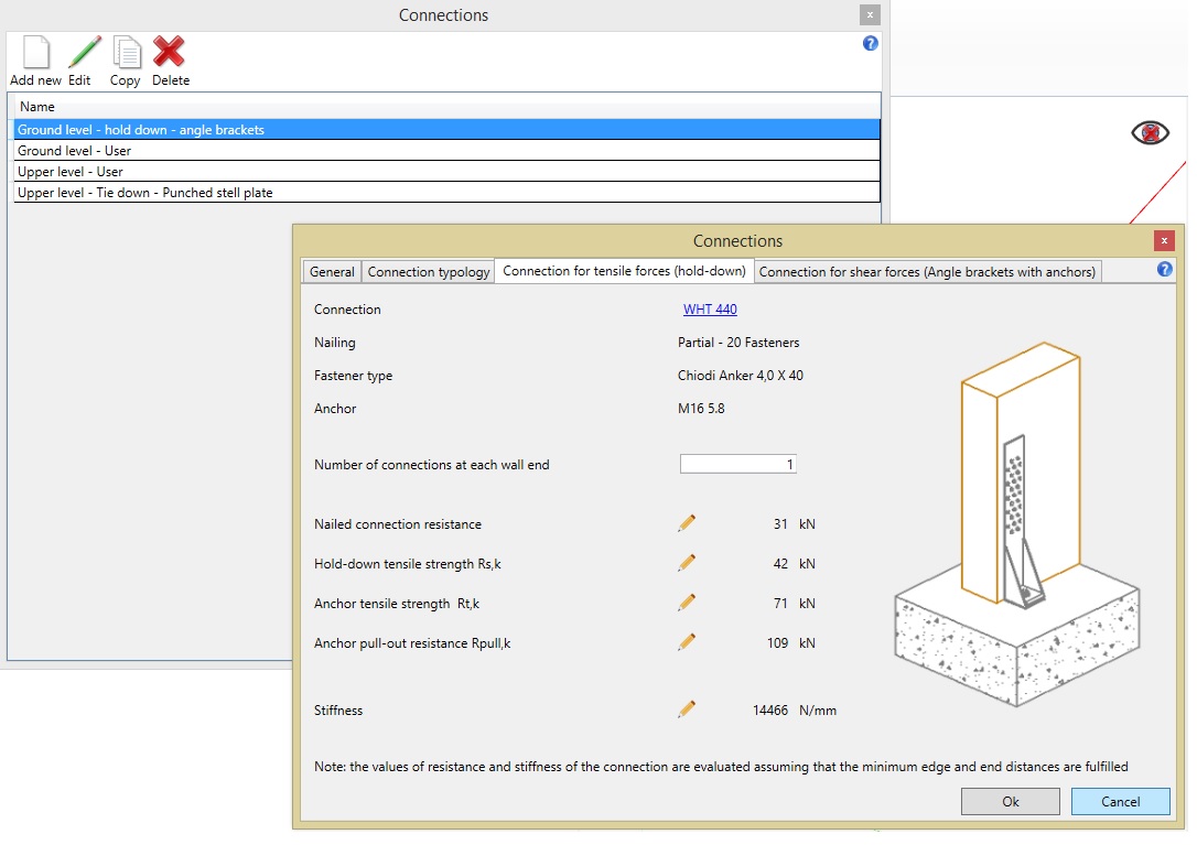
DEFINING THE connections PROPERTIES
The user can define in a simple and intuitive way the connections for shear and tensile forces both for ground floor or upper floors.
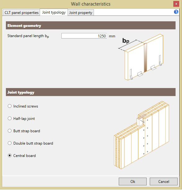
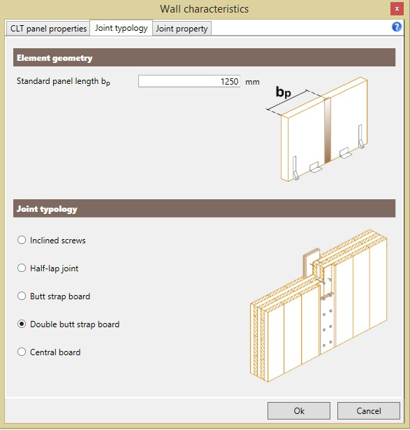
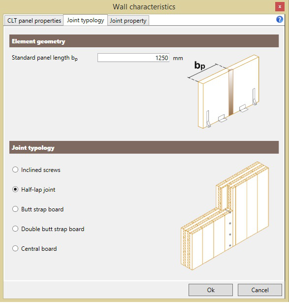
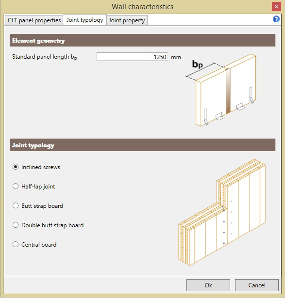
DEFINING THE PROPERTIES of the vertical joints in CLT walls
The software guides the user in the definition of the geometrical and mechanical properties of the CLT wall vertical joints.
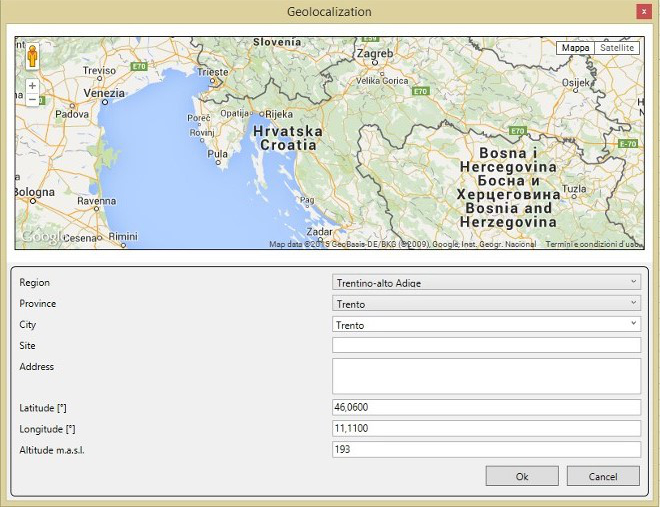
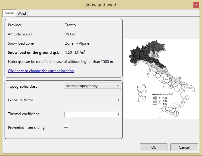
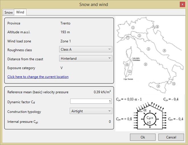
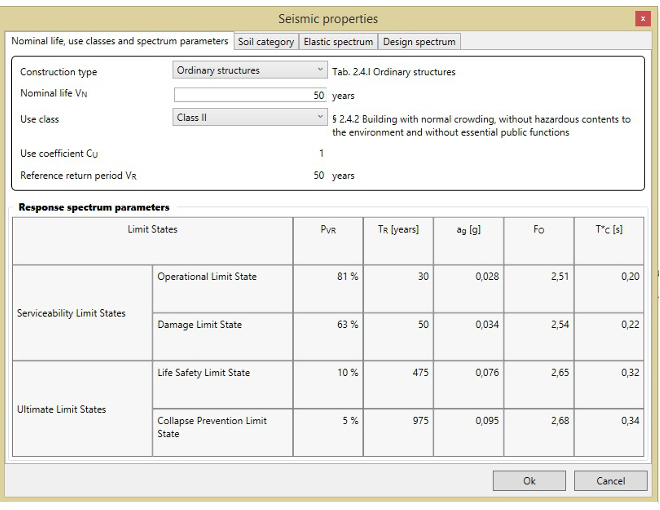
Automatic generation of loads
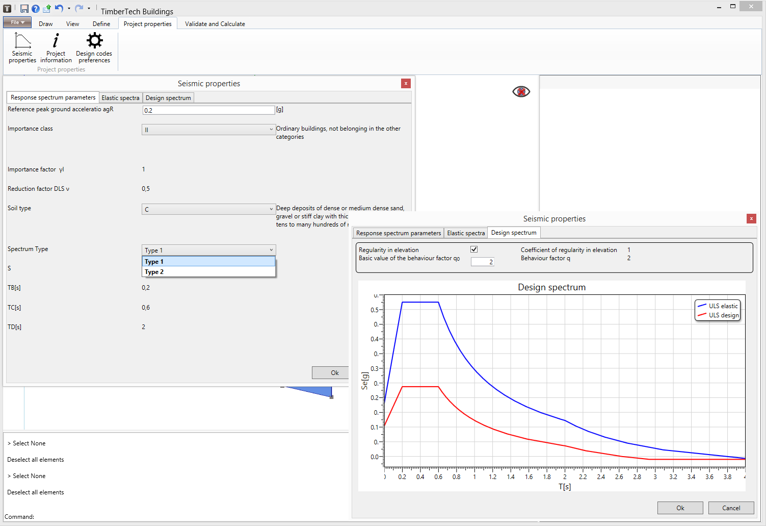
Snow load, wind load and seismic action are automatically generated according to the site where the structure is located and the selected Standard. The user only has to select the parameters that characterize the loads using a specific wizard.
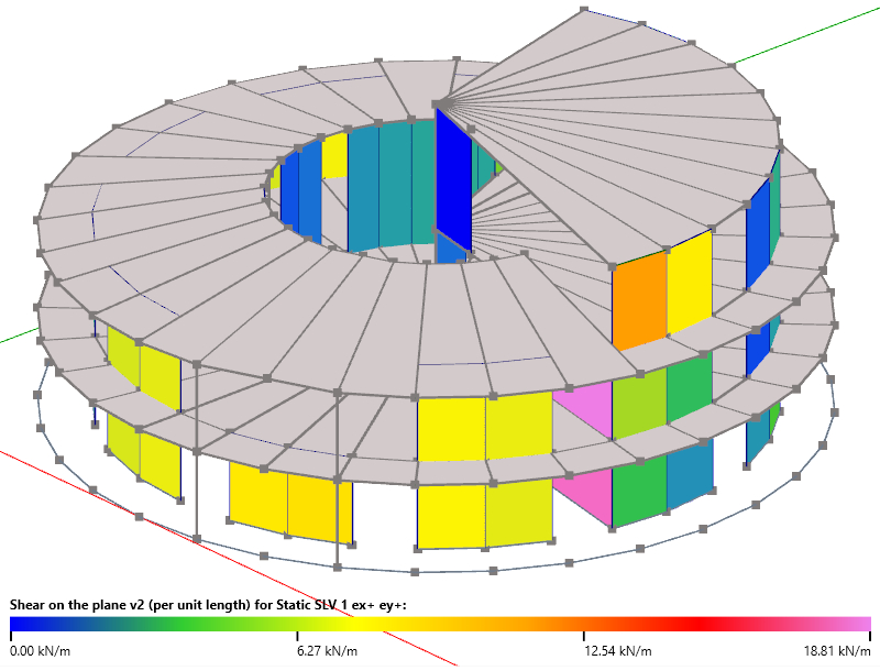
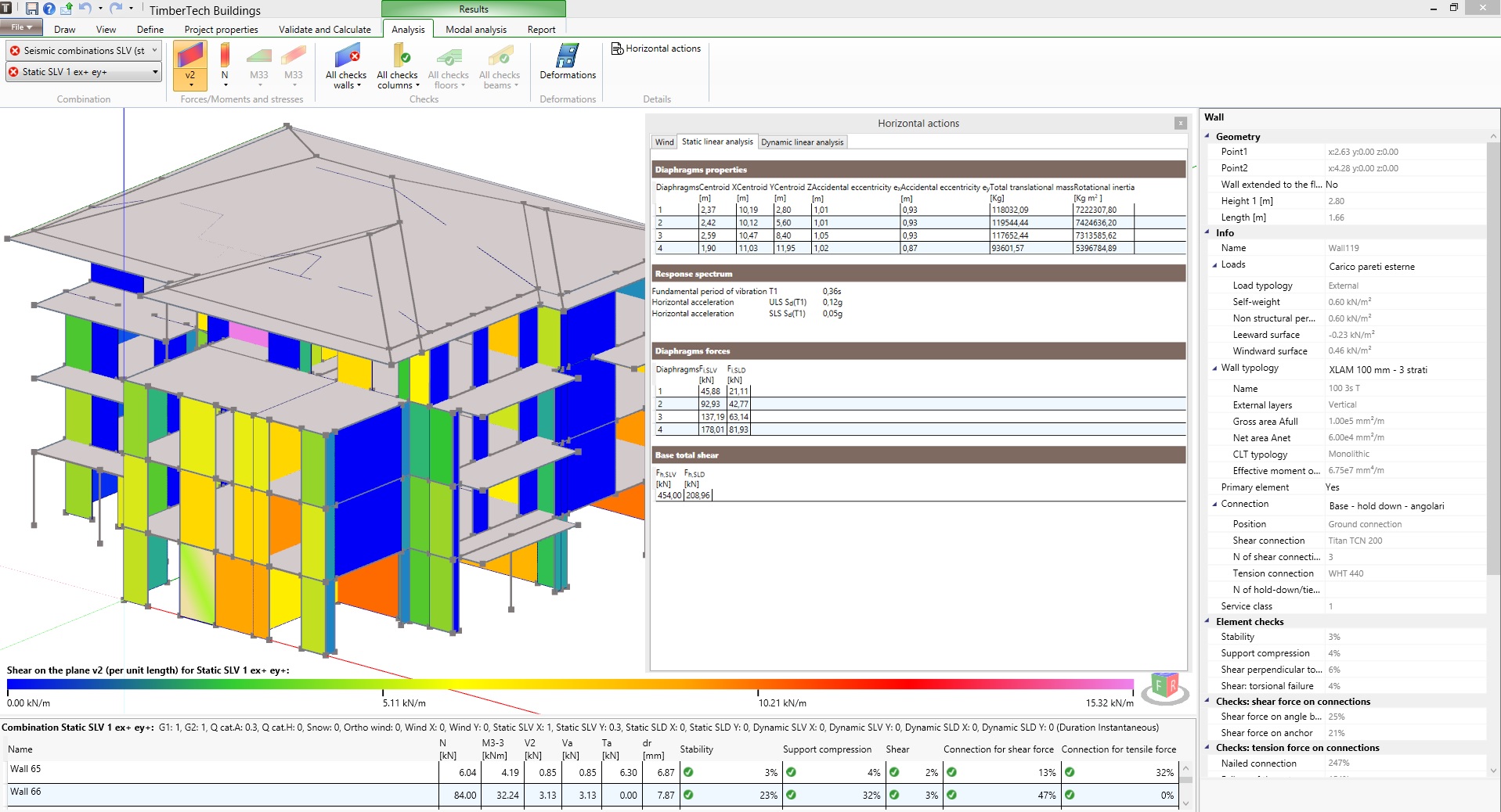
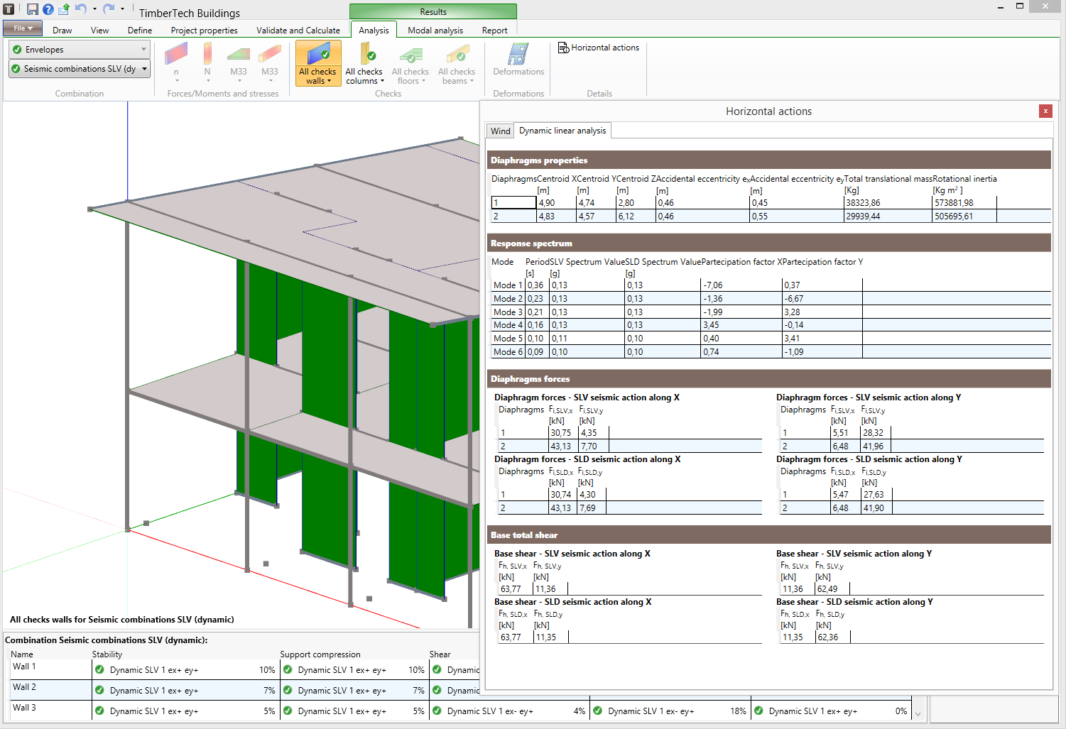
SEISMIC ANALYSIS
TimberTech Buildings performs the following types of seismic analysis:
- Equivalent linear static analysis
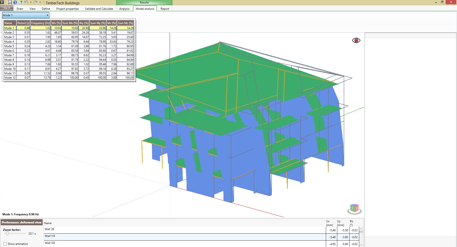
- Modal analysis, very useful to find the various periods at which a structure will naturally resonate. Mode shape can be displayed in a very simple way.
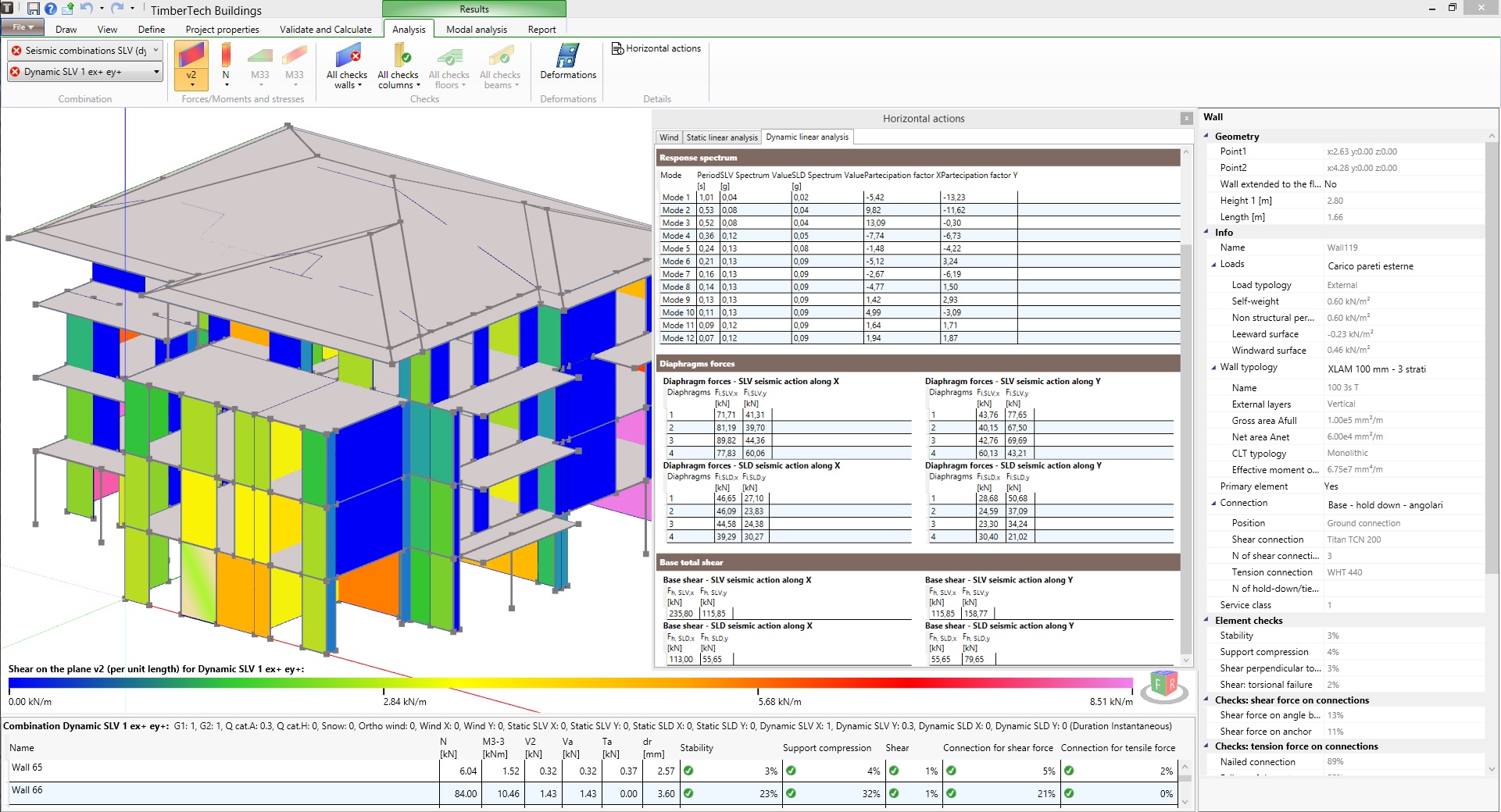
- Modal linear dynamic (response spectrum) analysis
The software automatically calculates the wall lateral stiffness also taking into account the contribution of the connections.

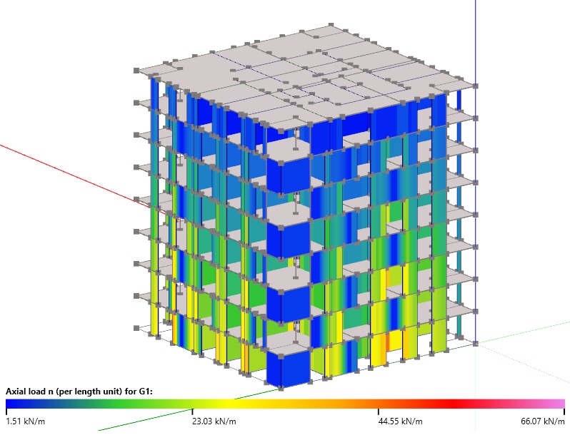
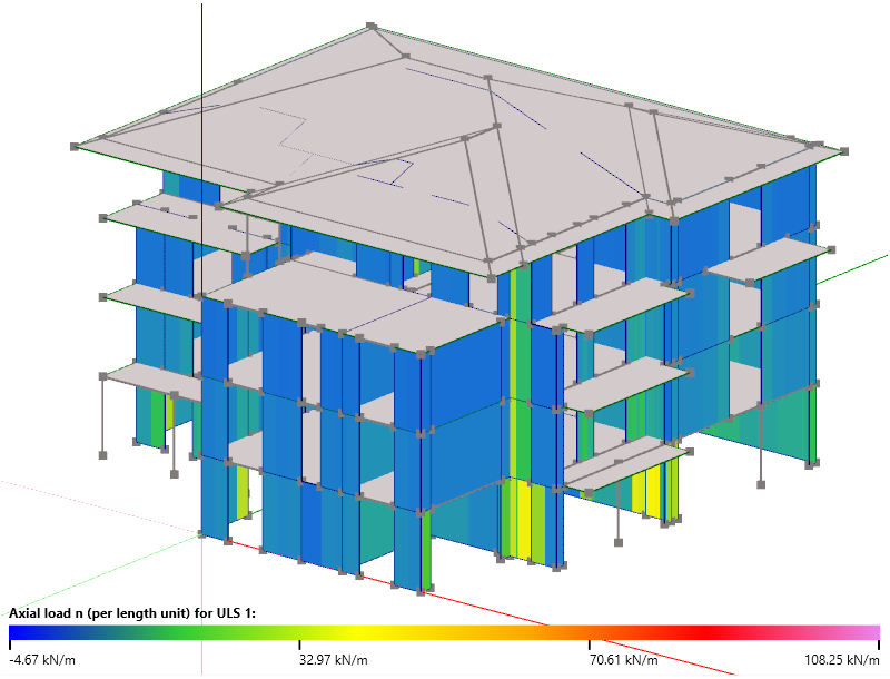
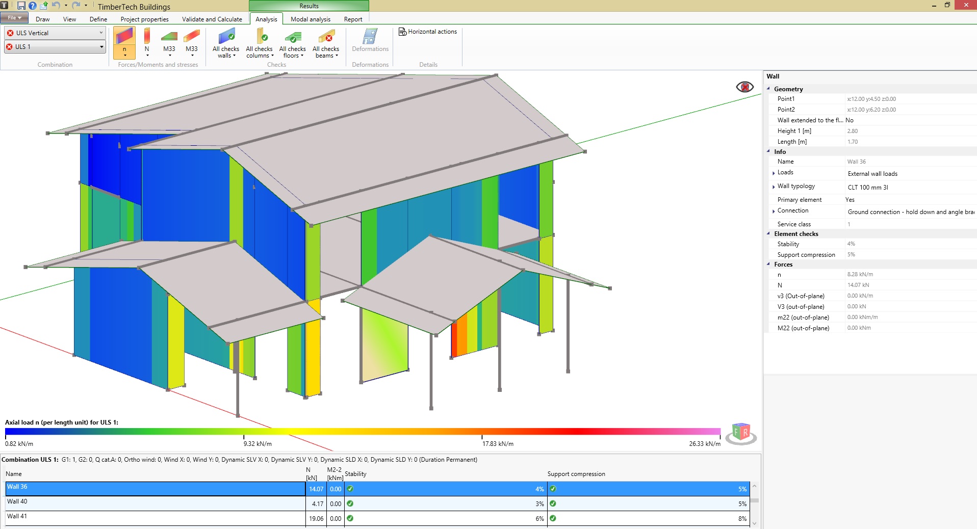
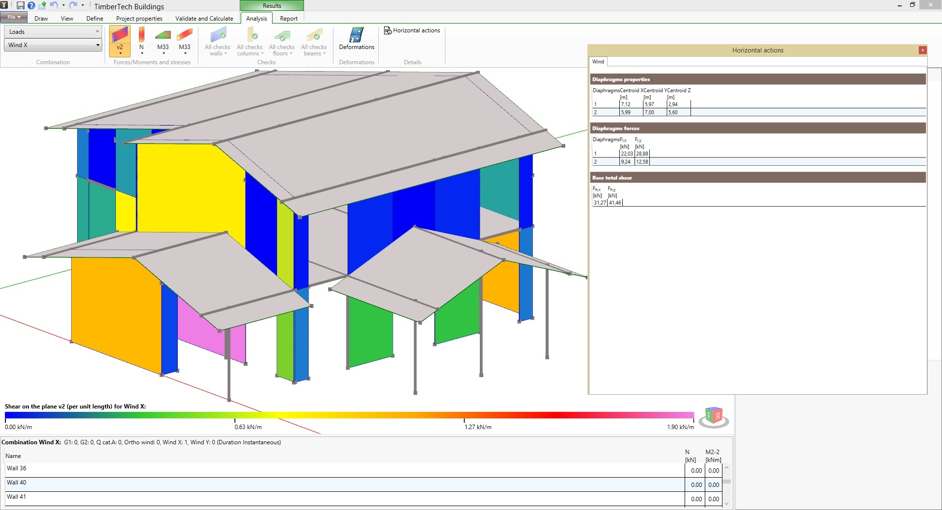
ANALYSIS FOR VERTICAL LOADS AND WIND
The software performs the analysis of the whole structure subject to the non-seismic loads (vertical gravitational loads and wind) which are automatically generated for each load combination prescribed by the selected Standard.

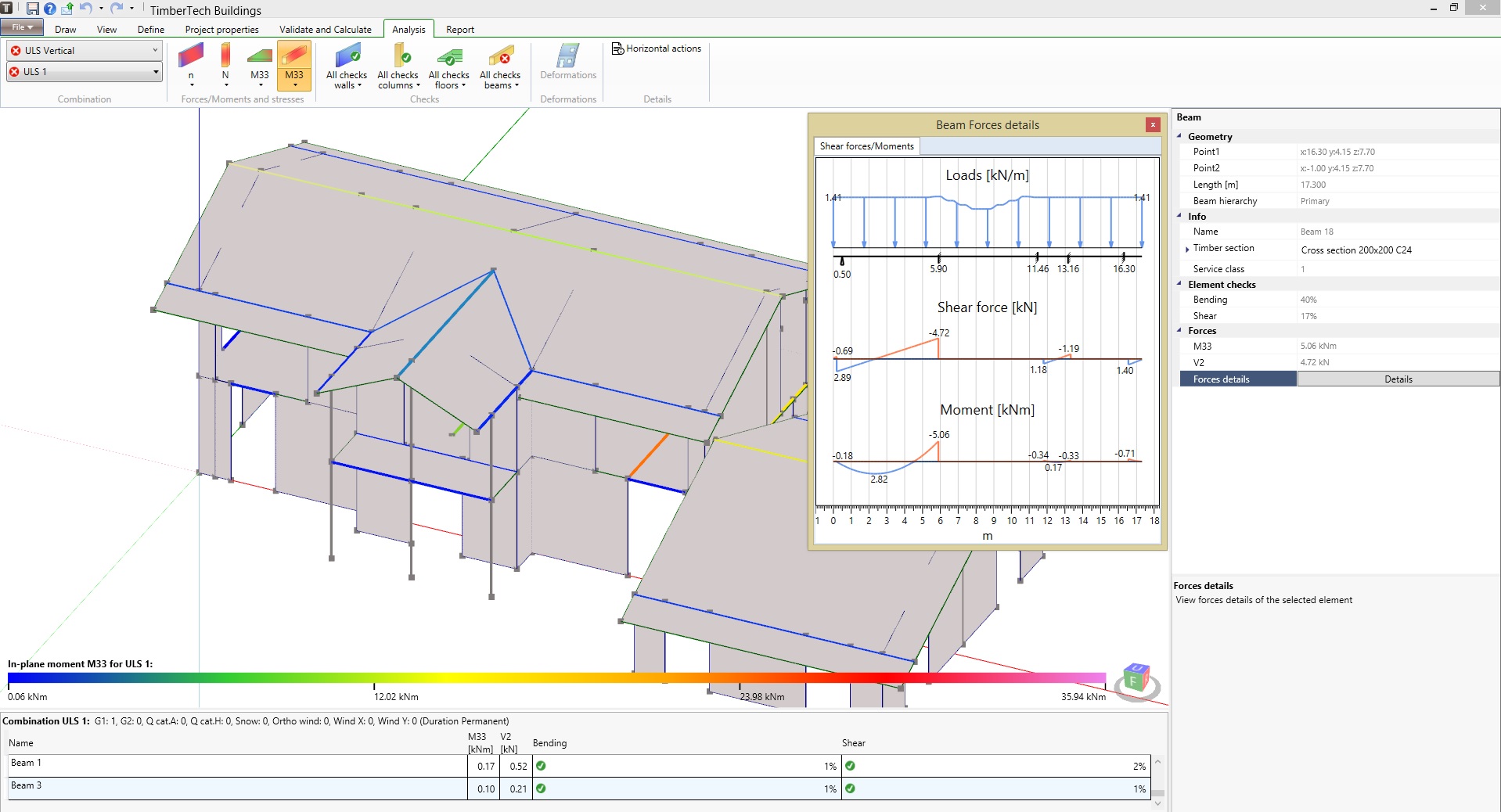
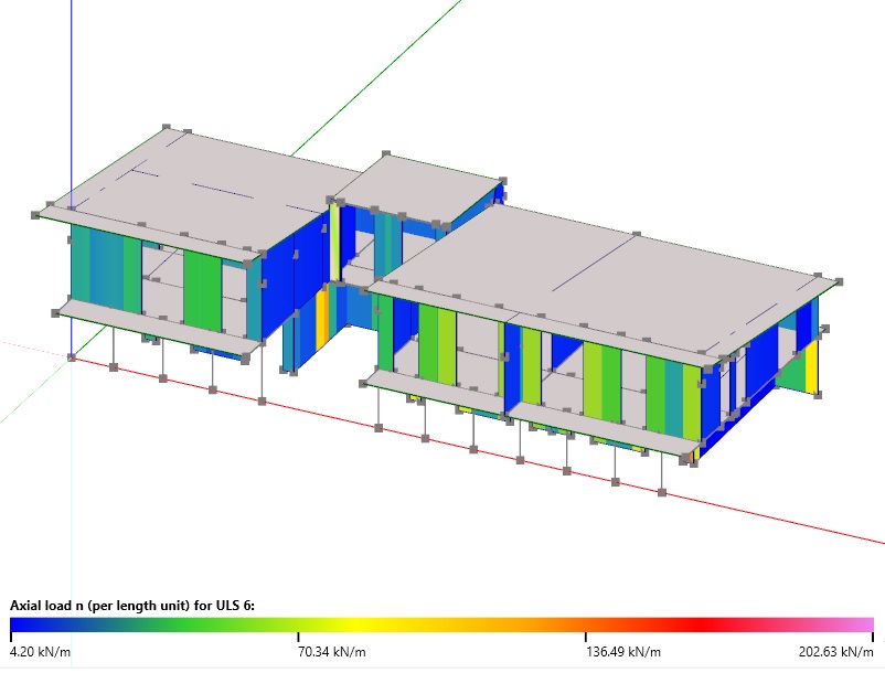
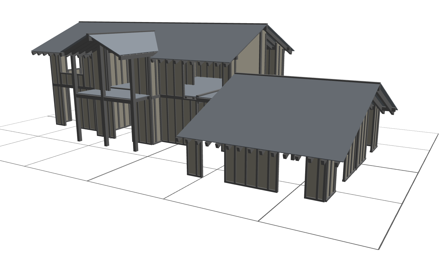
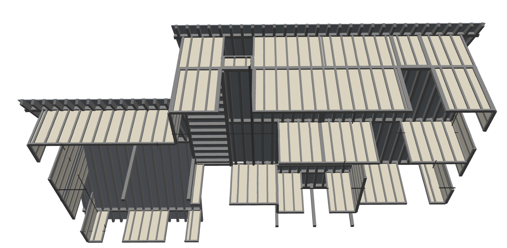
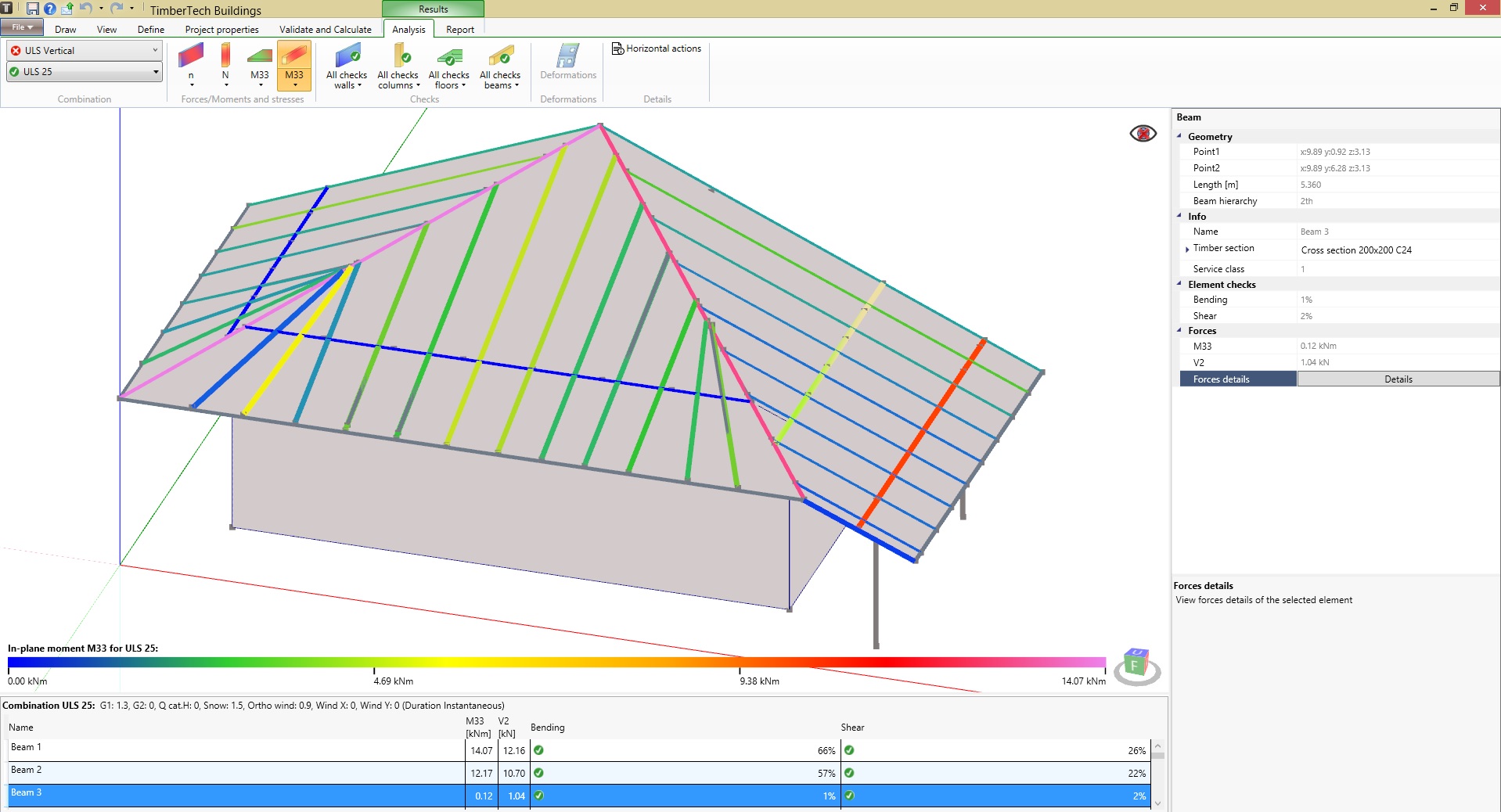
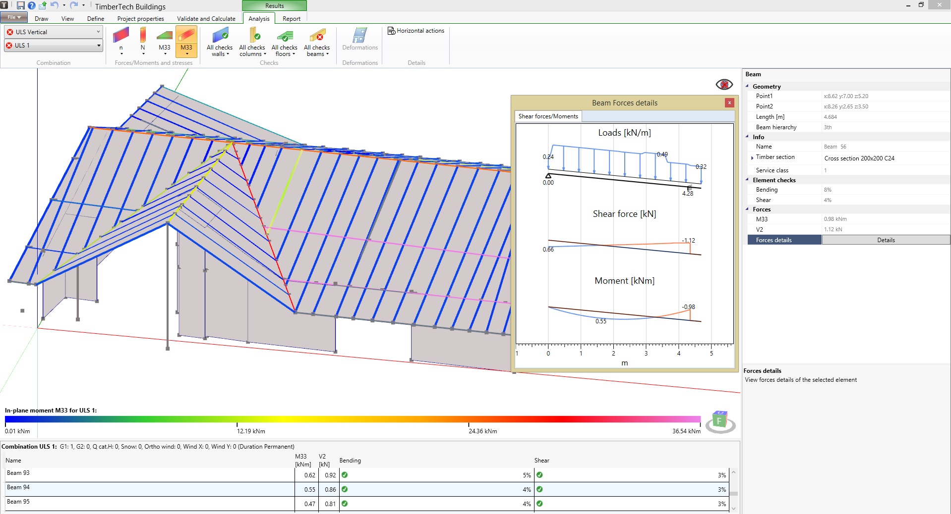
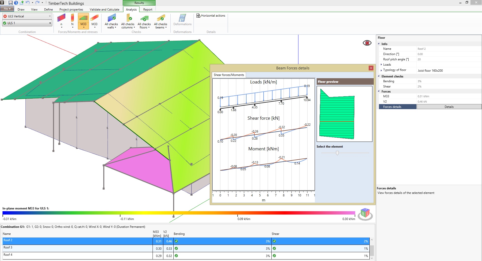
roof design
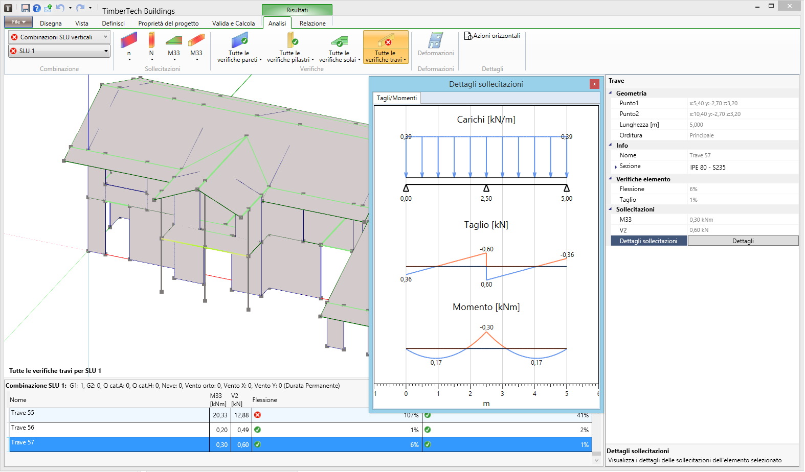
The software allows to model pitched roofs, performing the calculation and the automatic redistribution of loads acting on the beams and the joists which can have any inclination within the roof plane.

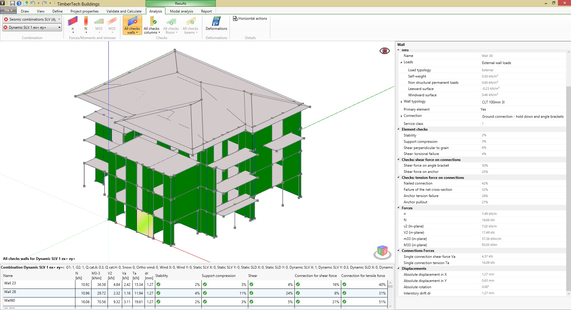
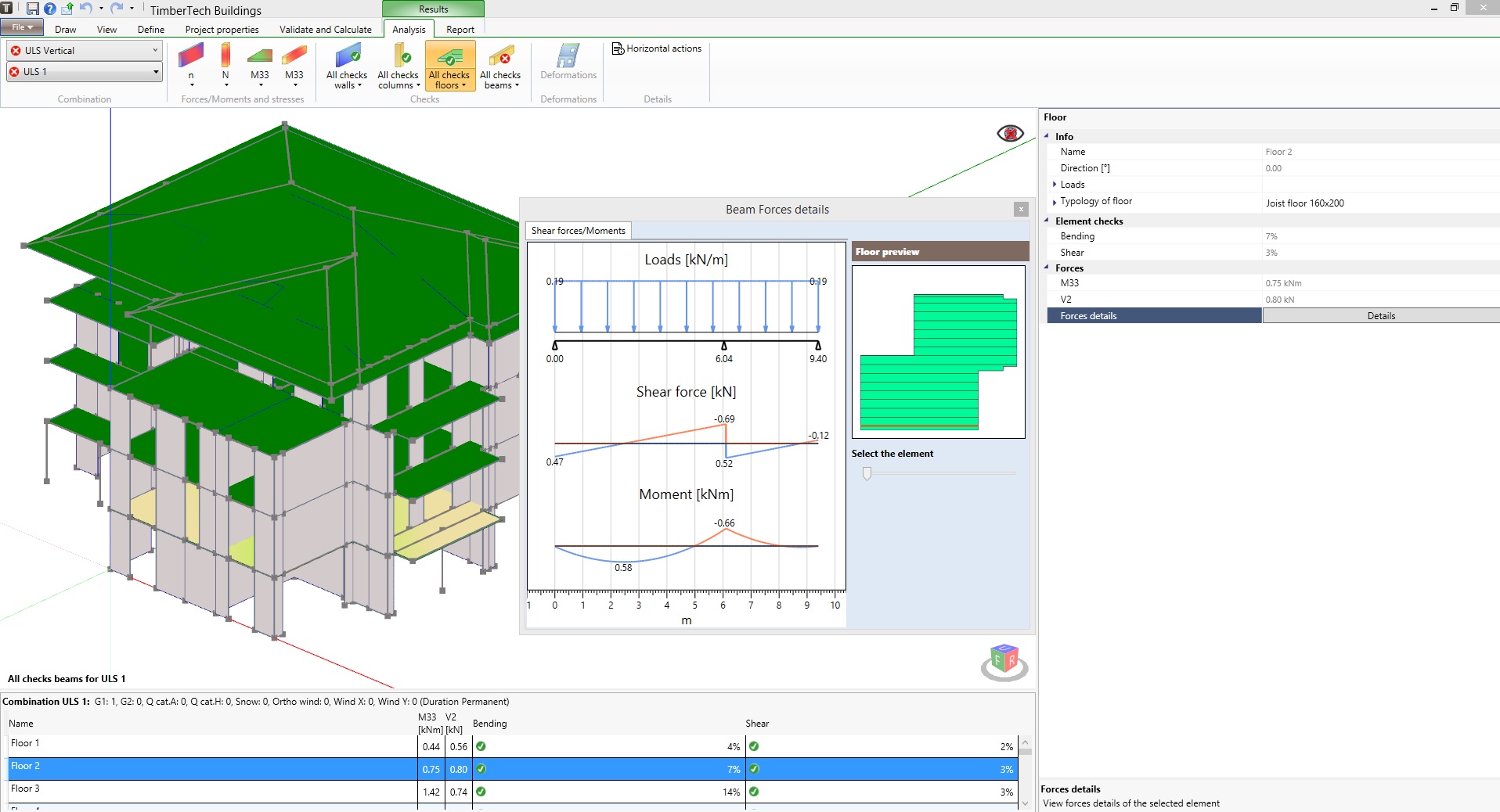
CHECKS
The program performs the checks, both static and seismic, of all the elements constituting the structure:
- CLT walls and their internal joints
- framed walls and their internal elements: timber frame and sheeting panels
- connections: hold-down, metal angle brackets, punched metal plates and straps, screws, nails and staples
- timber beams and columns
- timber ceilings: CLT floors, joists floors, solid timber floors
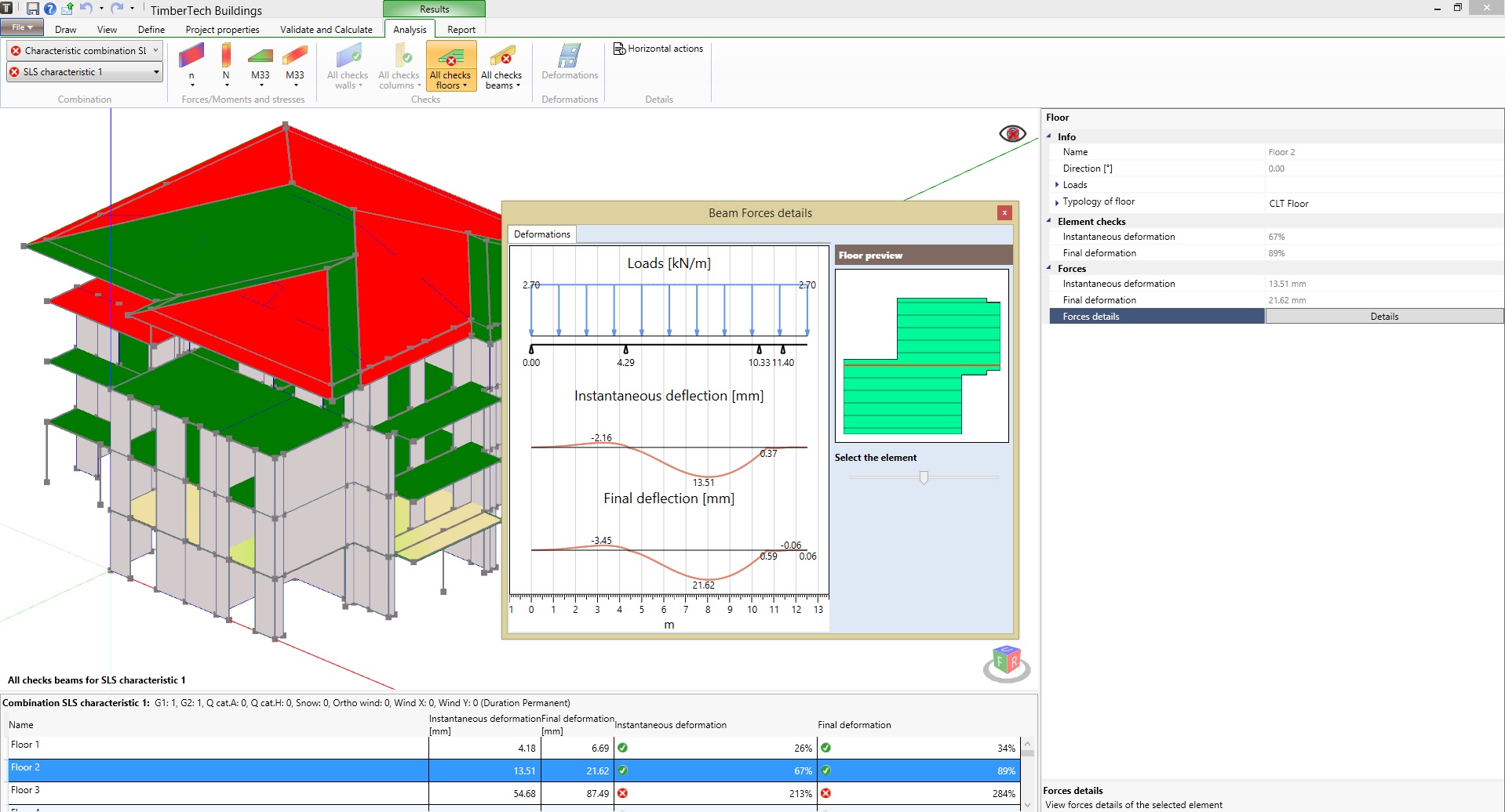

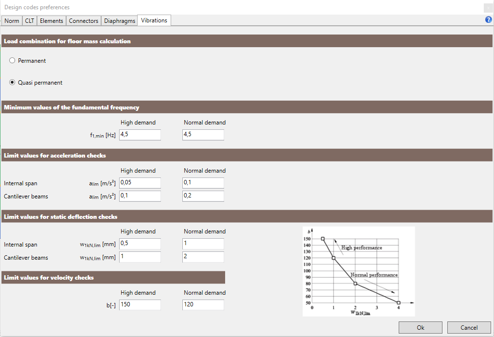
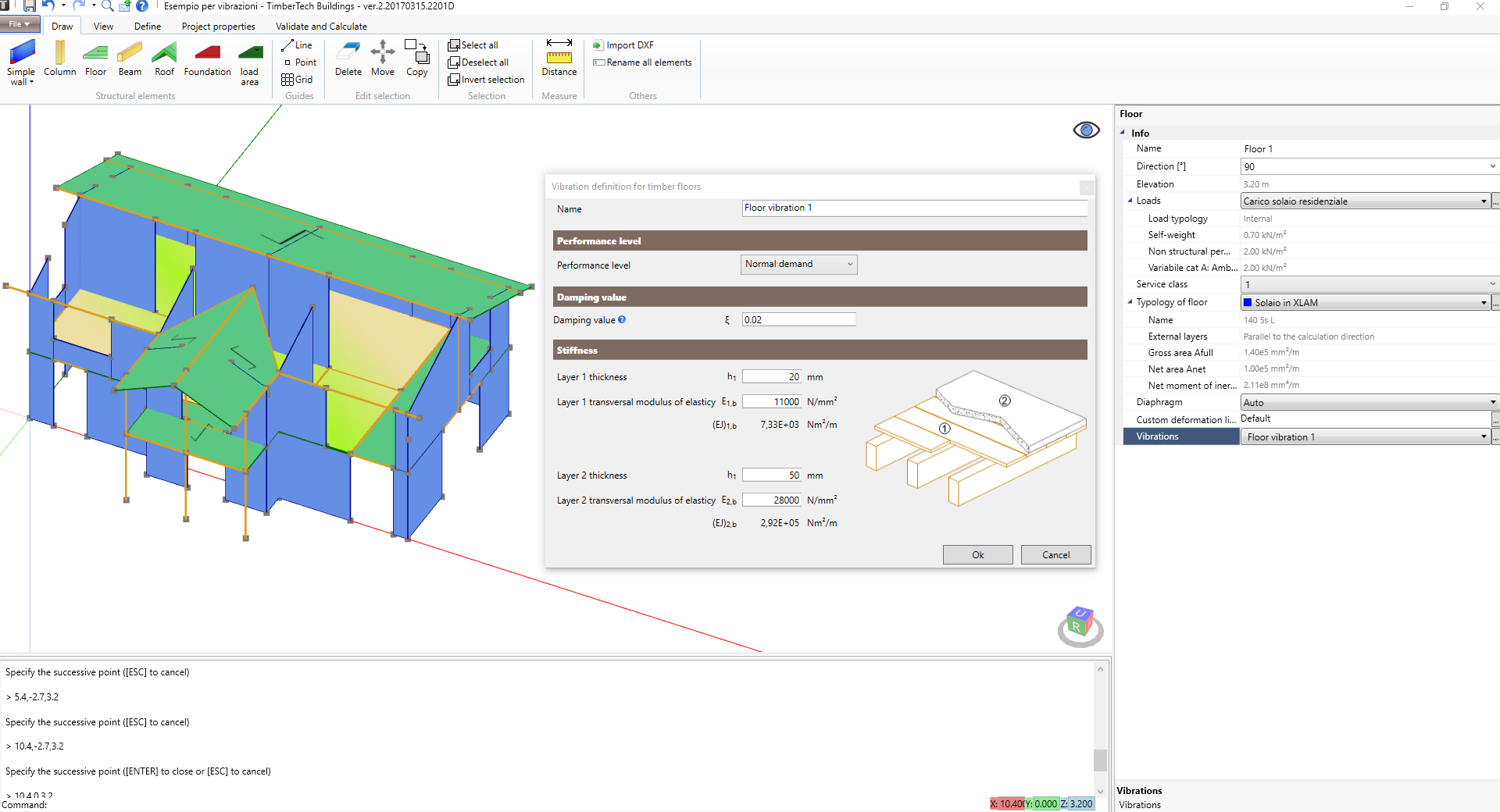
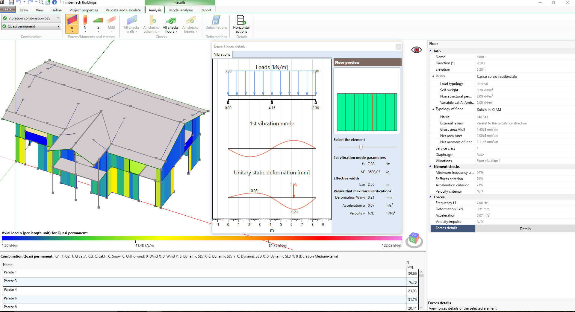
FLOOR VIBRATIONS CHECKS
The software performs the floor vibrations checks(joist floors, CLT floors and solid wood floors). The checks are performed in a very accurate way, element by element; in particular the software detects the actual static scheme of every structural element and calculates the fundamental frequency of vibration f1. On the basis of the frequency f1 are then performed the following checks:
- stiffness criterion (deflection under a static concentrated load with intensity equal to 1 kN)
- acceleration criterion (for fundamental frequancy f1 less or equal to 8 Hz)
- velocity criterion (for fundamental frequancy f1 greater than 8 Hz, 7.3 – UNI EN 1995-1-1)

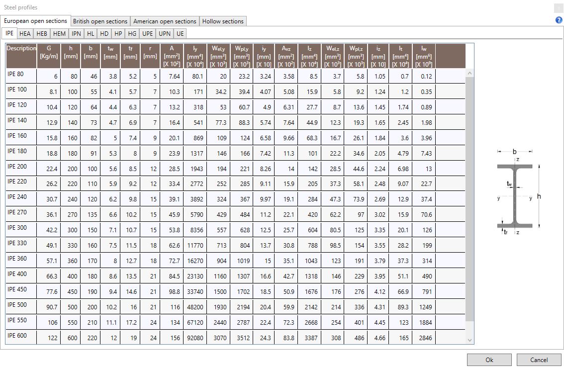
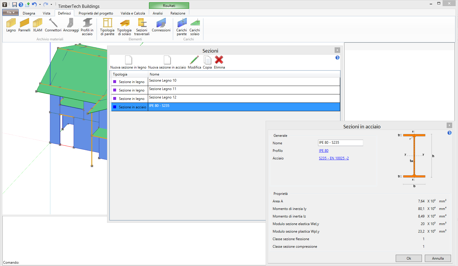
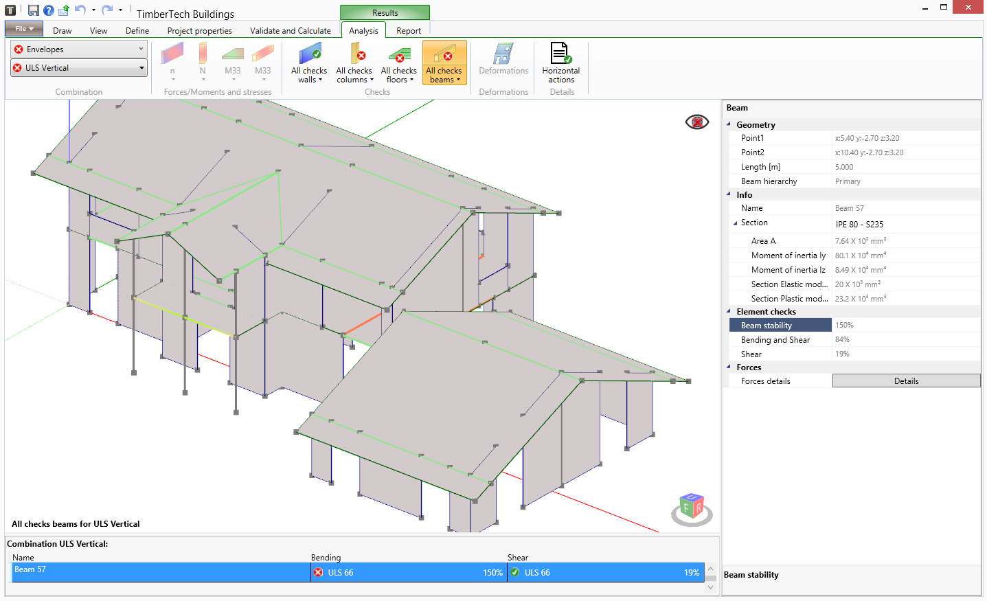
DEFINING the PROPERTIES and checks of the steel elements
The program performs checks of steel beams and columns for any cross section class. The properties of the steel cross-sections are preloaded in an internal database: European open sections (IPE, HEA, HEB, HEM, IPN, HL, HD, HP, HG, UPE, UPN, UE), British open sections (UB, J, UC, UBP, PFC), American open sections (W, S, HP, C, MC) and hollow sections (RHS, SHS and CHS hot-finished or cold formed)
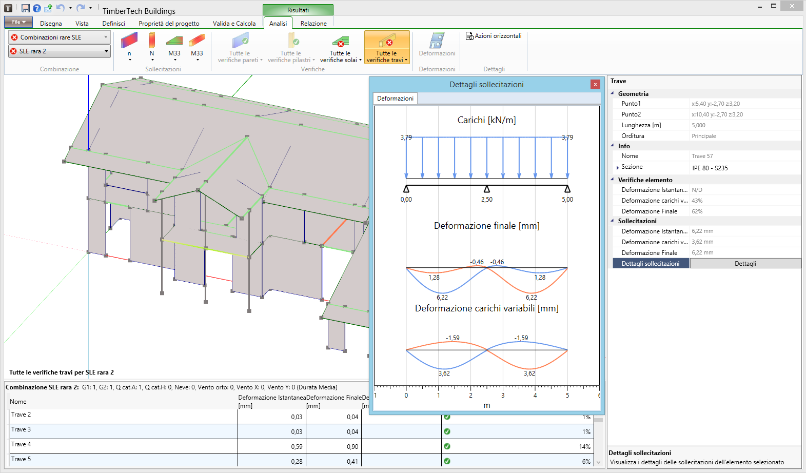
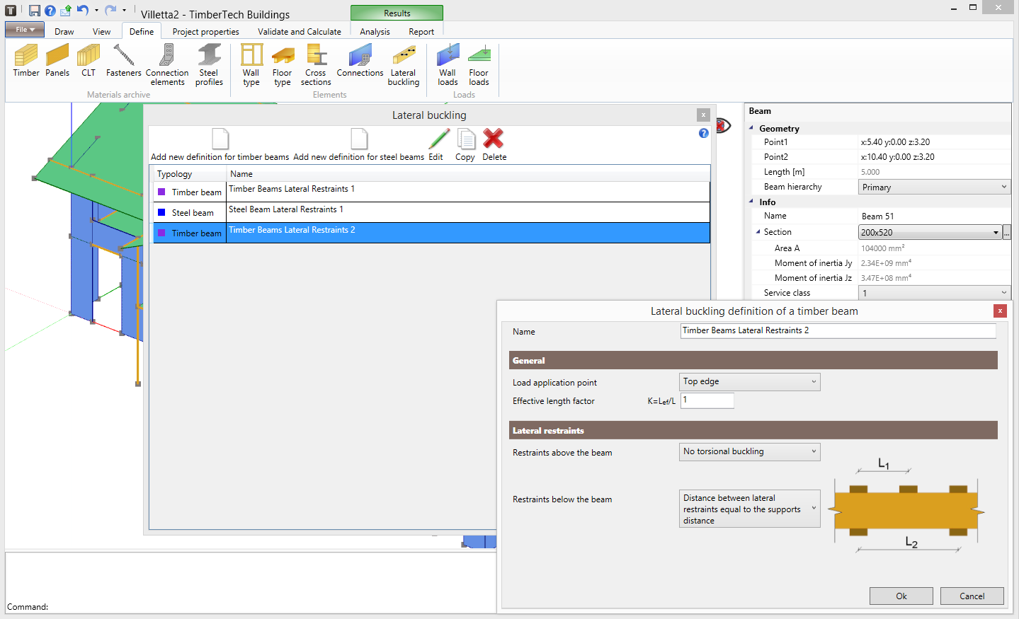
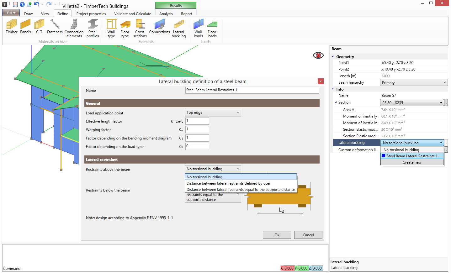
LATERAL BUCKLING CHECKS OF THE BEAMS
The software performs the checks of the timber and of the steel beams considering the lateral buckling resistance. The user can quickly define the lateral restraints and all the parameters needed to checks the element.

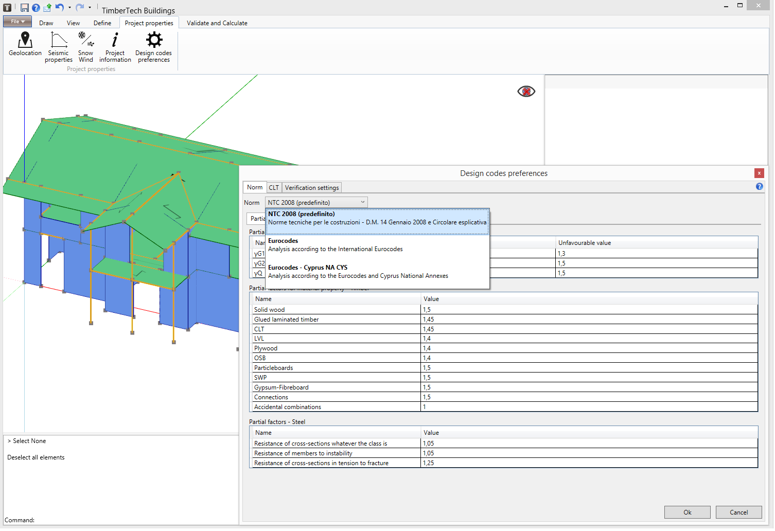
CHECKS according to different standards
The program performs checks according to the following National Codes:
 Italian National Code, NTC 2018
Italian National Code, NTC 2008
and according to the Eurocodes and to the following National Annexes:
 EC, International Version
 NA Austria
 NA Cyprus
 NA Greece
 NA Germany
 NA Finland
 NA United Kingdom
 NA Bulgaria
 NA Denmark
 NA Estonia
 NA France
 NA Latvia
 NA Lithuania
 NA Netherlands
 NA Norway
 NA Poland
 NA Portugal
 NA Romania
 NA Spain
 NA Sweden
 NA Switzerland

SUPPORTED LANGUAGES
The user can choose from the following languages for the use of the software and for the printout of the calculation report:
English
 Czech
Czech
 French
German
Greek
Italian
Polish
Portuguese
Spanish
design calculation report
The software automatically generates a clear and detailed technical design calculation report which can be exported in Microsoft Word format.
Technical report – CLT structure
Technical report – platform frame structure
Extract from the report – dynamic analysis
Extract from the report – floor vibrations
EXPORT REACTIONS IN FOUNDATION
According to each load and load combination, the software allows to export the actions on the foundation, in csv format, both as forces at the midpoint of each wall and as distributed forces along the length of the walls. This export, together with that of the geometry of the foundation, will be useful for designing the foundation with a dedicated software.
Foundation geometry – DXF export
Foundation reactions – CSV export
IMPORT & EXPORT of drawings in AUTOCAD DXF FORMAT
The software is able to import 3D DXF files in order to help the designer to draw the geometry of the structures.
Moreover, the distribution of the columns and the shear walls with the detail of the connections can be exported in a dxf file provided with legend indicating the number and type of connections used. Finally, it is possible to export a DXF file that contains the geometrical characteristics of floors, roofs and all their components.